The Storage Tile
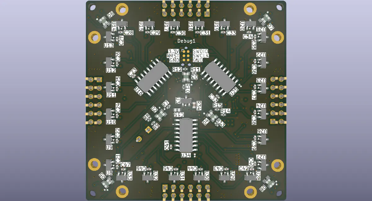
Building a physical inventory system for an engineering workshop
I wanted to make physical workshop inventory behave more like a searchable engineering database.
In a typical workshop, finding a component means remembering which drawer, box, or shelf it was placed in. Even when everything is physically organised, the information surrounding it datasheets, CAD files, manufacturer information, specifications, and inventory state usually lives somewhere else.
The Storage Tile is my attempt to connect those two worlds.
The idea is to build a modular storage system from inexpensive 60 × 60 mm PCB tiles. Each tile can identify the storage container sitting on it, communicate with neighbouring tiles, indicate its location with LEDs and a buzzer, and report meaningful state changes to a larger database system.
The eventual goal is simple: search for a component through the engineering platform, press Locate, and have the physical storage location identify itself.
The Problem
The original problem was straightforward:
I wanted drawers that knew what was inside them.
The challenge was making that idea scalable.
I didn’t want every drawer to have a fixed address and require manual configuration. Instead, I wanted identical modules that could be arranged into different configurations and automatically discover the resulting layout.
A storage container should therefore be able to answer:
- What is this container?
- Where is it?
- Is it still there?
- What is stored inside it?
- Where is the component I’m looking for?
Design Goals
The system developed around several requirements:
- A tile must fit within a 60 × 60 mm footprint.
- Tiles must be inexpensive enough to build into a useful-sized system.
- Containers should not require their own electronics.
- Containers should be identifiable from their physical position.
- Tiles should communicate with neighbours in four directions.
- The grid should discover its own topology.
- Individual tile failures should not necessarily disable the entire system.
- Most decisions should happen locally rather than constantly involving the server.
- The hardware should integrate with a larger inventory and engineering database.
- The architecture should allow future features without making them mandatory.
There was also a less measurable goal: use the project to push my PCB design skills.
The result became as much an exercise in compact PCB and distributed-system design as it was an attempt to solve workshop storage.
The 60 × 60 mm constraint
Almost every design decision is influenced by the 60 × 60 mm tile.
The board needs to accommodate:
- 24 Hall-effect sensors
- An STM32 microcontroller
- Four UART interfaces
- LEDs
- A buzzer
- Power conversion and protection
- Connectors
- Mechanical mounting
- Future expansion
At the same time, it needs to remain inexpensive enough to manufacture in quantity. A component being $0.20 more expensive is insignificant on a one-off prototype. Across hundreds of tiles, however, that decision becomes important. The system therefore needs to be optimised for the cost of the complete system, rather than the cost of an individual PCB.
Three-layer physical architecture
The module is built around a stack of PCBs.
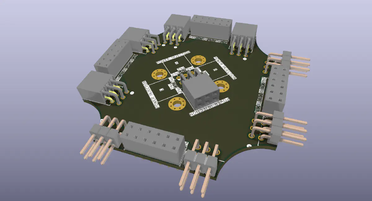
Power backplane
The bottom board is a 24 V power backplane. It mounts to the storage structure using screw standoffs and provides the electrical and mechanical foundation for the tile.
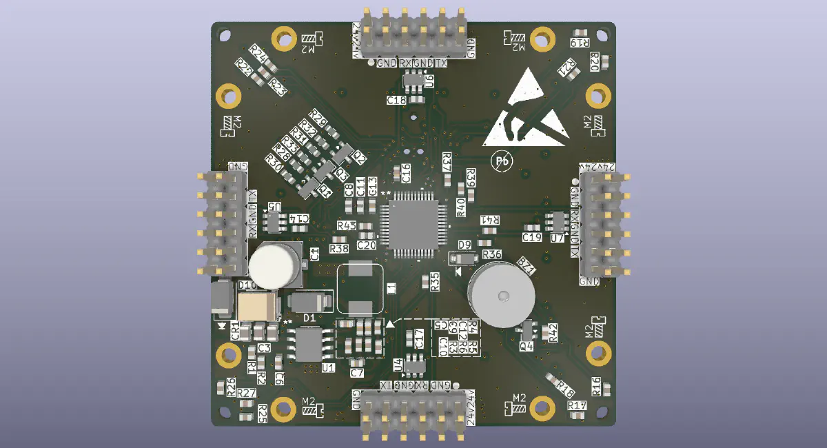
Brain board
The middle PCB contains the main electronics. At its centre is an STM32G071CBT6 microcontroller responsible for container detection, identification, neighbour communication, LEDs, the buzzer, local state, failure detection, and communication with the larger system.
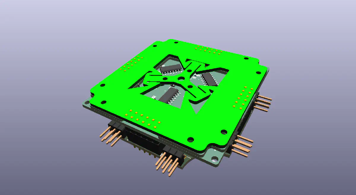
Experimental expansion layer
The upper section is intended for experimental features, including a possible PCB-based weighing mechanism. This is deliberately not part of the core architecture. If the weighing mechanism proves impractical, it can be replaced by a conventional rigid plate without affecting the rest of the system.
Why the STM32 and UART?
The STM32G071CBT6 isn’t the cheapest microcontroller available, but its capabilities allowed me to remove other hardware.
The board uses four independent UART interfaces:
- UART 1 → North
- UART 2 → East
- UART 3 → South
- UART 4 → West
An earlier design considered CAN. CAN would have been attractive for a larger distributed system, but putting a transceiver on every tile added cost and didn’t fit the failure behaviour I wanted. The tiles are only 60 mm apart, so neighbouring boards can communicate over extremely short connections. That makes UART a reasonable architectural trade-off.
Instead of paying for a dedicated CAN transceiver on every tile, the system uses functionality already inside the STM32 and keeps the physical communication distance very short.
This became an important component-selection lesson:
The cheapest individual component isn’t necessarily the cheapest system.
Automatic topology discovery
Each tile has four communication directions:
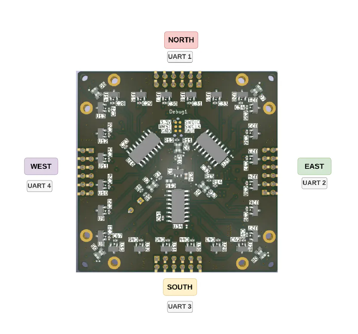
When the 24 V system starts, each STM32 identifies itself and discovers which neighbours are connected.
The basic process is:
Tile starts → Identify itself → Discover neighbours → Exchange topology information → Report to server → Server builds grid map
The important distinction is between local reality and global state.The tile knows about its own identity, neighbours, container, sensors, LEDs, buzzer, and local failures. The server knows about the complete grid, container locations, inventory, components, CAD files, datasheets, and other engineering information. This keeps the tiles relatively autonomous while allowing the server to maintain the overall warehouse model.
Designing for failure
A distributed storage system needs to account for failed modules. Imagine a 10 × 10 grid where one MCU dies in the middle. The desired behaviour isn’t:
One board died, therefore everything after it is disconnected.
Instead, the failed tile should become a hole in the network. Neighbouring tiles can identify that something is missing, and the overall topology can be updated. The exact routing algorithm is still being developed, but the four-way architecture provides several possible ways to route around failed cells. It also makes physical maintenance straightforward. A failed tile could be identified by its surrounding indicators, replaced, and allowed to rediscover the network. The goal is therefore a system built around replaceable modules rather than a monolithic controller.
Identifying the storage containers
The storage containers use a simple magnetic identification system. The brain board contains 24 Hall-effect sensors arranged around the perimeter of the tile. The container has small magnets positioned underneath it. A magnet represents a binary state, producing a magnetic pattern that acts as a digital identifier:
Magnet pattern → 24 Hall sensors → 24-bit state → Validation → Container identity
Approximately 16 bits are expected to provide the main identification, with additional bits available for redundancy and validation. Parity can be used to detect invalid readings, allowing the system to distinguish between:
No container and A container is present, but its code is invalid.
This approach was chosen instead of RFID because the storage geometry is extremely compact. Hall sensors are inexpensive, require no electronics inside the containers, and fit naturally into the PCB.
The storage containers
The current prototypes are 3D-printed 60 mm cubes with recessed positions for the magnets. The container feet fit into the PCB geometry for self-alignment. The container can also be rotated by 90 degrees while remaining identifiable through its magnetic coding.
For production, I plan to investigate 60 mm extruded non-magnetic tube, cut to different lengths. This could allow the same PCB interface to support containers such as:
- 60 × 60 × 60 mm
- 60 × 60 × 120 mm
- 60 × 60 × 180 mm
The PCB defines the interface while the container scales vertically.
Experimental weighing
One of the more experimental features is estimating how much material remains inside a container. Instead of using a conventional load cell, the PCB itself becomes part of the mechanical system. A cut pattern allows controlled flexing while keeping most of the board rigid. A hard stop limits deformation to approximately 1.5 mm.
The concept is:
Container weight → PCB flexes → Magnet displacement → Hall sensor → Measured displacement → Estimated weight
The target maximum load is approximately 900 g per cell, although this still needs experimental validation. The goal isn’t necessarily laboratory-grade weighing. Even reliably detecting that material has been removed could be useful. Importantly, this remains an experiment. If the PCB spring isn’t sufficiently predictable, it can simply be replaced by a rigid plate.
Power and PCB architecture
The storage grid uses a 24 V power backplane to make larger installations practical. Each brain board locally generates its 3.3 V supply using a TPS54331D buck converter. The power architecture was designed with expansion in mind. A 10 × 10 grid is the initial target, while a few hundred boards is a more realistic upper scale before additional power injection and network infrastructure become necessary. The brain board also includes a SMBJ26A TVS diode for protection against power transients, cable transients, ESD, hot-plugging, and other abnormal voltage events.
The brain board is a four-layer PCB:
- Layer 1 — Signal
- Layer 2 — GND
- Layer 3 — PWR
- Layer 4 — Signal
The four-layer construction isn’t primarily about high-speed signalling. The board is small and heavily routed, so the internal ground and power planes provide valuable routing space and cleaner return paths. The PCB is also part of the mechanical structure. The brain board connects to the backplane through 6 × 2 pin connectors on each side. The additional pins provide mechanical support, multiple power paths, and ground connections around communication signals. Cheap connectors were chosen deliberately because the system isn’t intended to be repeatedly plugged and unplugged hundreds of times.
Local intelligence
The STM32 performs as much processing locally as possible.
It handles:
- Container detection
- Hall sensor processing
- Container ID validation
- Container removal detection
- LED and buzzer control
- Neighbour failure detection
- Local communication
The server handles global commands and system state. For example, there is little value in continuously transmitting all 24 raw Hall sensor readings. The STM32 can interpret them locally and communicate meaningful events instead. This makes the system less dependent on constant server communication and leaves network capacity for useful messages.
The Storage Tile is part of a larger software system using PostgreSQL. The backend models storage grids, cells, containers, locations, nodes, links, sensors, device capabilities, commands, detection events, measurements, and warehouse operations. The wider engineering platform also contains information about components, manufacturers, datasheets, CAD files, suppliers, inventory, and other engineering data. This creates the connection between a digital engineering record and a physical component. A component can have its manufacturer, part number, specifications, datasheet, CAD model, inventory information, and physical container location associated with it. The Storage Tile then provides the physical location.
Finding a component
There are two intended workflows. The first is simple: walk to the storage system, find the container, and take the component. The Storage Tile detects the change and updates the inventory state. The second is the searchable workflow. A user searches for a component in the engineering platform and selects Locate. The system determines the container’s current location and sends a command to the relevant tile. The tile then flashes its LED and sounds its buzzer, identifying the physical location. The goal is for physical inventory to behave more like a searchable engineering database.
Current state
The project is currently at the hardware prototype stage.
The following have been designed and manufactured:
- 60 × 60 mm brain board
- 60 × 60 mm 24 V power backplane
The boards have been assembled into their intended grid arrangement to verify the mechanical geometry and stacking concept.
The electronics have not yet been fully populated and tested.
That leaves several important questions:
- Does the Hall-effect identification work reliably?
- Is the magnetic coding tolerant of physical variation?
- Does the four-way UART network behave as expected?
- How reliable is topology discovery?
- How well does the system handle failed nodes?
- Is the PCB spring predictable enough for weight estimation?
- Are the component choices and PCB layout correct?
- Is the overall architecture unnecessarily complex?
These are the next engineering questions rather than problems being hidden by the prototype status.
Next steps
The next stage is hardware bring-up.
First, the boards need to be populated and the 24 V power system, protection circuitry, buck converter, and 3.3 V rail validated. The STM32 can then be programmed and its GPIO, UART, and other peripherals tested. Next, all 24 Hall sensors need to be characterised using the first magnet-coded containers. This should establish how reliable the identification system is under real mechanical tolerances. Multiple tiles can then be connected to test neighbour discovery, topology mapping, and failure handling. The experimental PCB spring will also be tested under different loads to determine whether the weighing concept is useful enough to retain. Finally, once the physical network is reliable, the tile state and container locations can be integrated with the PostgreSQL warehouse system.
Conclusion
The Storage Tile started with a simple idea:
I wanted drawers that knew what was inside them.
It has developed into an exploration of how physical storage can become part of a larger engineering information system.
The key connection is:
Physical component → container → storage tile → network → database → engineering information
The 60 × 60 mm tile is the physical building block that makes this possible. It combines sensing, processing, communication, power, mechanical structure, and human feedback into a repeatable module. The first boards are now manufactured. The next step is to discover whether the design works as well in hardware as it does on paper. That is where the interesting engineering begins.